
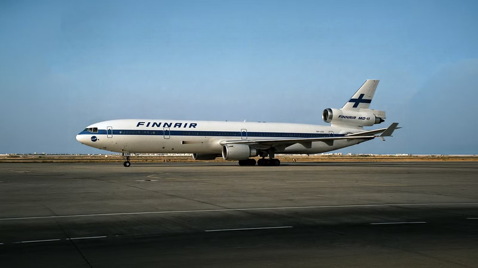
The unmistakable silhouette of the McDonnell Douglas MD-11 is defined by the massive third engine piercing through its vertical stabilizer. While other trijets like the Lockheed L-1011 TriStar tucked their center engines deep inside the fuselage using curved S-ducts, McDonnell Douglas opted for a straight path. This guide uncovers the engineering trade-offs behind that choice and explains how this straight-pipe layout impacted the aircraft’s performance.
Understanding the tail-fin engine is key to understanding the MD-11’s identity as a long-haul workhorse. Most aircraft of its era were either twin-engine or four-engine designs, leaving the trijet as a unique middle ground. Choosing a straight-through duct over a curved S-duct was a calculated move to maximize thrust and minimize the weight penalties associated with complex ducting.
Middle Engine Innovation?

In the world of high-speed aerodynamics, air movement can be quite complex. The MD-11’s No. 2 engine, located at the base of the vertical stabilizer, features a direct, straight-line intake that allows air to enter and exit without any deviation. This differs significantly from the S-duct found on the Boeing 727 or the Lockheed TriStar, which forces air through a complex curve to reach an engine buried in the tail cone.
The primary advantage of this straight-through configuration is the preservation of intake pressure. When air is forced through an S-shaped curve, it encounters friction and centrifugal forces that create turbulence and dead spots before the air even reaches the engine’s fan blades. By utilizing a straight duct, the MD-11 ensures the engines receive a uniform, high-pressure stream of air, maximizing thrust during critical phases like takeoff.
Engineers refer to this as maximizing total pressure recovery, and it plays a major role in the aircraft’s fuel burn over 10 to 12-hour routes. While an S-duct allows for a lower engine placement, making it easier for ground crews to reach, it creates a permanent tax on engine performance. McDonnell Douglas prioritized raw power and efficiency, even though it meant mounting a 9,000-lb engine over 30 feet above ground and reinforcing the entire tail structure to support it.
Relying On Understanding Physics

The sheer size of modern turbofan engines played a decisive role in why the S-duct design fell out of favor for large widebody aircraft. When the MD-11 was being developed, it required massive high-bypass engines like the General Electric CF6-80C2 or the Pratt & Whitney PW4460 to carry heavy loads across global routes. These engines have fan diameters of nearly 94 inches, making them significantly larger than the engines found on older trijets like the Boeing 727.
Attempting to curve a column of air that is almost eight feet wide through an S-shaped tunnel would have required a gigantic, heavy duct. The weight penalty of the structural reinforcement needed to house such a large, curved pipe inside the fuselage would have stripped away the aircraft’s payload capacity. By opting for a straight-through design, McDonnell Douglas kept the fuselage narrower and avoided the massive aerodynamic drag that a structurally complex and large S-duct tail would have produced.
This straight-pipe philosophy also ensures the engine operates at peak performance throughout the entire flight. According to NASA, high-bypass engines are sensitive to any disruption in the air entering the fan, and a straight intake provides the most stable environment possible. On long-distance routes, this stability prevents the engine from working harder than necessary, resulting in better fuel economy and less wear on internal components.

The Striking Differences Between The McDonnell Douglas DC-10 & MD-11
Discover how the DC-10 and MD-11 reshaped wide-body design, defined the trijet era, and why their legacy still lingers in today’s skies.
When Maintenance Finds New Alternatives

Servicing the center engine of an MD-11 is a task that literally takes aircraft maintenance to new heights. The powerplant is integrated directly into the vertical stabilizer, and so mechanics have to perform their work nearly 30 feet above the ground. This extreme height requires specialized equipment, such as massive, custom-built scaffolding, which can make a routine inspection much more complex than on a standard twinjet where engines sit just a few feet off the ground.
Ground crews at major cargo hubs have developed a specialized routine for these high-altitude repairs, often working on these aircraft during scheduled downtime at facilities in Memphis or Louisville. While the height is a logistical challenge, the straight-through design actually offers a significant accessibility advantage once the crew reaches the work platform. Unlike an S-duct engine that is buried deep within the tail cone of the fuselage, the MD-11 tail engine is wrapped in simple, side-opening cowlings that provide an unobstructed view of the entire engine core.
|
Task Category |
Standard Under-Wing Engine |
MD-11 Tail Engine |
|
Working Height |
5 – 10 feet |
25 – 35 feet |
|
Equipment Needed |
Standard ladders / stands |
Scaffolding / Cherry pickers |
|
Core Visibility |
High |
High (Unobstructed) |
|
Engine Removal |
Hoist to ground |
Dropped vertically via hoist |
The ability to drop the engine straight down into a cradle using a specialized hoist system simplifies major engine swaps compared to the puzzle extraction required for an S-duct. Even though the mechanics are working at a height that might make some people very dizzy, the simplicity of the straight-pipe layout means they aren’t fighting through tight internal spaces or complex, curved ducting. This trade-off is one of the reasons the MD-11 remains a viable, albeit demanding, aircraft for specialized freight operators on long-distance routes.
Only For Skilled Pilots

Placing a massive jet engine directly in the middle of the vertical stabilizer creates a unique challenge for directional control that a standard aircraft never has to face. The engine housing occupies the central space where a traditional one-piece rudder would usually hinge, meaning that the tail design had to be fundamentally reimagined from the ground up. This placement results in the aerodynamic flow over the tail constantly interacting with the high-velocity exhaust from the center engine, requiring a robust solution to maintain stability during takeoff and landing on international routes.
Engineers solved this problem by splitting the rudder into two distinct sections: one located above the engine intake and one positioned below the exhaust nozzle. This dual-rudder configuration ensures that the pilot has sufficient yaw control even when the center engine is operating at maximum thrust. By separating the control surfaces, the MD-11 maintains its ability to crab into strong crosswinds without the engine housing blocking the necessary airflow over the moving parts of the tail.
|
Feature |
MD-11 Split Tail |
Standard Single Tail |
|
Rudder Type |
Dual-segment (upper/lower) |
Single continuous piece |
|
Surface Area |
Larger to compensate for gap |
Optimized for clean flow |
|
Control Complexity |
Higher (2 sets of actuators) |
Lower (Single system) |
|
Airflow Interaction |
Interacts with engine exhaust |
Clean aerodynamic flow |
The high placement of the engine introduces a specific pitching behavior that pilots must manage with a high degree of precision. Since the thrust is produced well above the center of gravity of the aircraft, adding power naturally pushes the nose of the plane downward. This characteristic requires more attentive control of the yoke, especially during the final approach to a runway, as any sudden increase in throttle needs to be countered with a corresponding pull on the controls to keep the flight path steady.

Is The McDonnell Douglas MD-11 Done Flying For Good?
The aircraft was once a long-haul workhorse.
Why Use This Design When It Causes Problems?

Many aviation fans ask why McDonnell Douglas stuck with a design that makes the aircraft so notoriously tail-heavy. When a 9,000-lb engine is perched at the very back of the fuselage, it shifts the center of gravity significantly rearward, which, to an observer, seems inherently filled with complications. This weight distribution is a defining characteristic of the MD-11, influencing everything from its takeoff rotation to the way it behaves during a landing flare on long-distance routes.
To manage this rear-heavy bias, engineers actually used it to their advantage to increase aerodynamic efficiency. By moving the center of gravity further back, they were able to reduce the size of the horizontal stabilizer by approximately 30% compared to the older McDonnell Douglas DC-10. A smaller tail surface creates less aerodynamic drag, which allows the plane to slip through the air more easily and save fuel. However, this also means the aircraft has a smaller margin for error during touchdown as well as a reduction in stability, requiring careful piloting and a sophisticated longitudinal stability augmentation system to help the pilot keep the pitch under control.
To keep the plane balanced as fuel is burned, the MD-11 features a dedicated fuel tank located right inside the horizontal stabilizer. This system allows the flight computer to automatically move fuel between the wings and the tail to maintain the optimal balance point throughout the flight. Crucially, this tank must be emptied before landing, shifting the weight forward to provide the pilot with better stability during the approach. It is a complex mix of weight and physics that ensures the straight-through engine design provides the necessary performance without compromising the aircraft’s stability, even when carrying a full load of heavy cargo.
Twin Engines Still Preferred

The straight-through engine design reached its peak with the MD-11, but the aviation industry was already moving toward a twin-engine future while this aircraft was still in production. As turbine reliability improved, the safety cushion provided by a third engine became less critical for long-distance routes over oceans. The mechanical complexity of mounting a massive turbofan in the tail could no longer be justified when two under-wing engines could do the same job with significantly less maintenance hassle and lower fuel consumption.
For cargo operators in modern times, the MD-11 is seen as a functional masterpiece precisely because of the power that the tail engine provides during heavy takeoff rolls. While the straight-pipe design creates a unique maintenance hurdle, the ability to lift massive payloads out of hot or high-altitude airports is a direct result of that efficient, direct-air intake. It serves as a reminder that engineering for raw performance often involves accepting logistical quirks that would not make sense in a standard passenger operation.
Looking ahead, it is unlikely we will see a return to the engine-in-fin layout for large commercial jets. Modern efficiency targets favor the simplicity of two engines, and the chapter of the tri-jet has effectively closed as MD-11s are gradually retired in favor of newer freighters like the Boeing 777F. The MD-11 remains a monument to a design philosophy that prioritized the physics of airflow above all else, leaving a lasting mark on the sky with its iconic, straight-through silhouette.