
 dailynewsnblog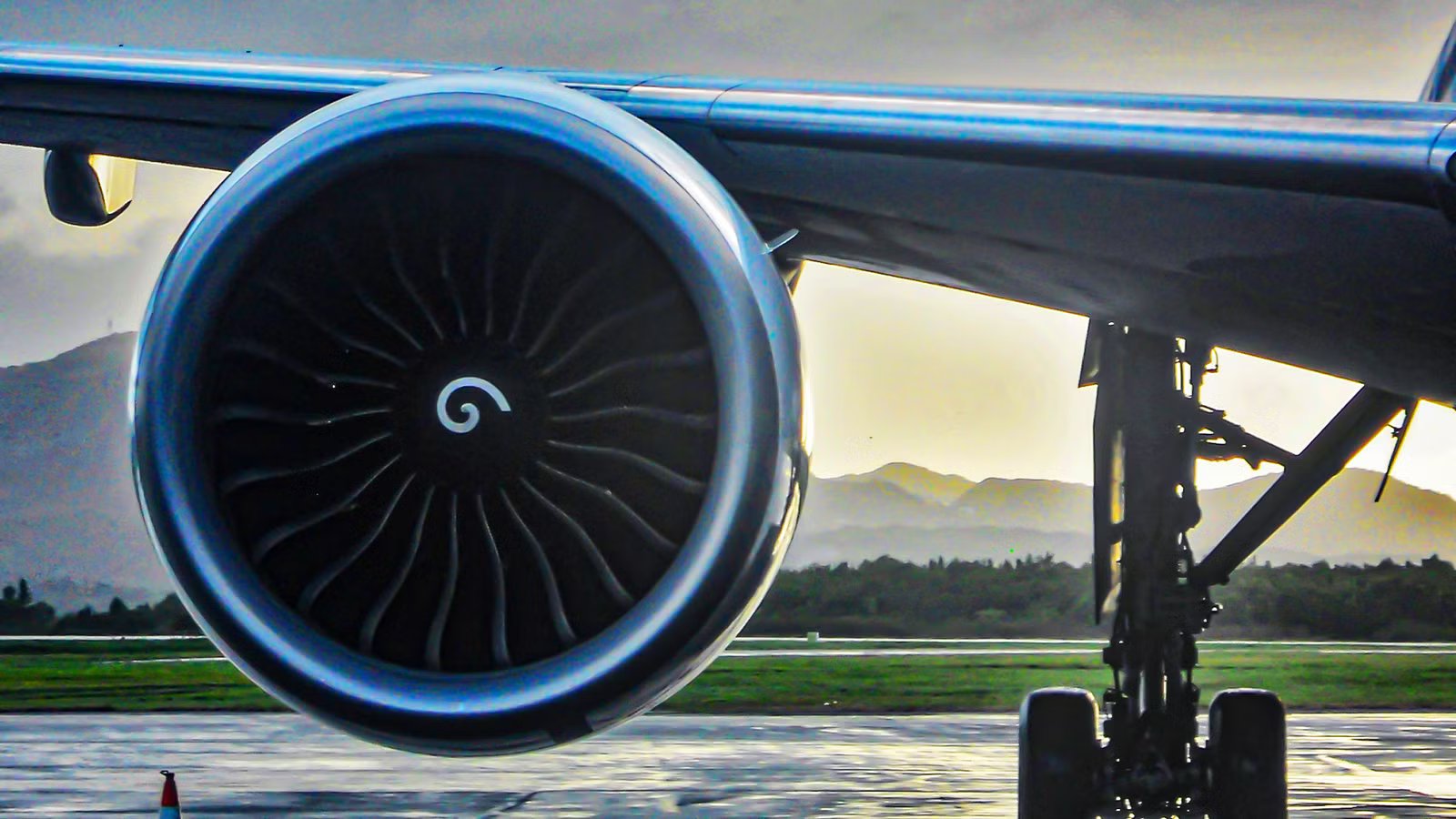
Commercial jets absorb a lightning strike once or twice per year on average, according to MiGFlug’s analysis of aviation lightning data, and no US commercial jet has been lost to a lightning strike since Pan Am Flight 214 went down in 1963 after a bolt ignited fuel vapor in a wing tank. That single accident, more than any other event in aviation history, is the reason every certified engine, nacelle, and fuel system flying today is engineered to treat a direct strike as a routine, survivable event rather than an emergency.
Here’s the number that actually matters: a powerful lightning stroke can involve currents approaching 200,000 amps, while the surrounding air channel can reach temperatures close to 54,000°F (30,000°C), nearly five times hotter than the surface of the Sun. And yet, in the overwhelming majority of cases, the pilots don’t touch the controls any differently, the engines never stop spinning, and the only proof anything has happened is a line in a maintenance logbook. By the time you finish this article, you’ll know exactly which parts of a modern jet engine take that current, where it goes, and what happens in the rare seconds when the fire actually does go out.
The Physics Of A Strike Meeting A Turbine

Lightning doesn’t strike an airplane at random; it attaches at specific points and exits at others, and a jet engine’s nacelle sits squarely among the likely candidates. Nose, wingtips, tail, and engine cowlings all rank as classic attachment or exit zones, because they’re the extremities that punch furthest into a charged cloud or trailing wake. Regulators formalize this into “lightning strike zones,” ranked by how directly a component is expected to be hit and for how long the current dwells there.
For an engine, that means the spinner, fan blades, and cowling lip typically sit in what’s called Zone 1A: a point of direct attachment where the full force of the strike arrives with no warning and needs to be conducted away immediately. The metal (or metal-lined) nacelle and engine mounts function as an extension of the aircraft’s Faraday cage, giving the current a low-resistance path from the point of contact, through the pylon, and back into the wing or fuselage structure, rather than letting it hunt for a path through fuel lines or wiring bundles. None of this is left to chance or assumption.
According to SKYbrary’s summary of lightning certification standards, manufacturers must map every one of these zones on a full-size aircraft model and validate them using waveform generators that simulate the current, voltage, and duration of a real strike, under the FAA’s Advisory Circular 20-136C and equivalent EASA rules. An engine design isn’t certified until it has demonstrated, on paper and on a test bench, that it can absorb a hit in Zone 1A without letting the current wander somewhere it shouldn’t.
Anatomy Of The Conductive Path: Bonding Straps And Static Wicks

Getting a 200,000-amp pulse to travel obediently from an engine cowling to a wingtip is less about any single component and more about thousands of small, unglamorous connections working together. Every panel, fastener, and structural joint on the nacelle and pylon has to be electrically “bonded” to its neighbor, so the strike sees one continuous conductor rather than a chain of tiny gaps that could arc, spark, or heat up on their own.
Engineers achieve this with braided metal bonding straps and jumpers that physically tie the engine case, cowl doors, thrust reverser sleeves, and pylon structure together, according to CThru Metals’ breakdown of aircraft lightning protection hardware. Any two adjacent metal surfaces that aren’t welded or riveted into a single structure typically get one of these straps, because even a fraction of an ohm of resistance across a gap can turn into a shower of sparks at 200,000 amps. Static discharge wicks, usually mounted on trailing edges, handle a gentler but constant job: bleeding off the ambient static charge an aircraft builds up simply from flying through the air, so it never accumulates enough to trigger a strike of its own.
This is also why an engine’s internal architecture matters. Because a modern turbofan is really three or four separate spools of rotating hardware, each spinning at its own speed, as detailed in Simple Flying’s article on turbojets versus turbofans, every one of those spools, along with the surrounding case and accessory gearbox, needs its own bonded path to the rest of the aircraft. A strike doesn’t care whether it lands on the fan, the low-pressure compressor, or the accessory drive; whichever component it hits needs a route out that doesn’t run anywhere near a fuel line or a wiring harness.
When The Fire Actually Goes Out: Inflight Relight

Even with a textbook-perfect conductive path, there’s one scenario lightning protection can’t fully rule out: the electrical effects of a strike can, in extremely rare circumstances, disrupt stable combustion inside the combustor and cause a flameout. It happens far less often than the popular imagination suggests, but it’s precisely the scenario every twin-engine airliner is certified to handle without drama.
Modern turbofans are designed and certified to keep burning through a strike in the vast majority of cases, and when a flameout does occur, many modern Full Authority Digital Engine Control (FADEC) equipped engines automatically command an in-flight relight when they detect a flameout, while others require the flight crew to initiate the restart. The system is built to recognize the loss of combustion within a second or two and begin an automatic relight sequence, reintroducing fuel and ignition to restart the core without waiting for a pilot to diagnose the problem. Airliners are certified for in-flight restart within a defined relight envelope specifying the combination of altitude and airspeed under which a restart has been demonstrated.
Crews are trained to recognize the failure, confirm the automatic relight is in progress or initiate a manual one, and continue toward their destination or a diversion airport, generally without needing anything more dramatic than a routine engine restart checklist. The redundancy engineered into these systems echoes the same reliability-first philosophy behind some of the most durable engines in commercial aviation, including the three-shaft Rolls-Royce RB211, profiled in Simple Flying as a turning point for engine durability standards.
Fuel Tanks And Nacelles: Preventing The 1963 Nightmare

Everything discussed so far protects the engine itself, but the more dangerous risk has always been what sits next to it: the wing fuel tank. Pan Am Flight 214’s 1963 crash happened because a lightning-induced spark inside a fuel tank’s vapor space ignited the fumes, and every fuel system certified since has been built with memory of that event, making that specific failure mode essentially impossible. A few years before, in 1959, TWAFlight 891, a LockheedL-1649A Starliner that had taken off from Milan Malpensa Airport(MXP), was doomed by an electrical discharge in the storm it was flying through, which ignited fuel vapor escaping from a vent on one of the wing fuel tanks, causing the destruction of the airframe.
Fuel tanks near engine pylons now use lightning-tested sealants around every access panel and fastener, bonded covers that maintain electrical continuity even where a panel has to be removable for maintenance, and nitrogen-based fuel tank inerting systems that reduce the oxygen content in the tank’s vapor space below the threshold needed for ignition. According to SKYbrary’s certification overview, this combination of bonding, sealing, and inerting has to be demonstrated for every fuel tank location a manufacturer expects lightning current might pass near, not just the tanks directly beneath a likely strike zone.
Long-range business jets making the same transatlantic hops as commercial airliners face identical convective weather and identical certification requirements, whether the aircraft is a widebody flying a scheduled route or a private charter like the ones detailed in Simple Flying’s breakdown of New York-to-London private jet charter costs. Since fuel tank and engine lightning protection standards apply by aircraft category, they don’t relax simply because the cabin happens to be smaller.
Composite Skins Change The Rules: The 787’s Copper Mesh Answer

A reasonable question follows from all this: if aluminum is such a good conductor, doesn’t building an airplane mostly out of carbon fiber composite make it more vulnerable to lightning? The short answer is yes, unless engineers compensate for it, which is exactly what happened as composite fuselages moved from experimental programs into mainstream jets like the Boeing 787 and Airbus A350.
Carbon fiber reinforced plastic conducts electricity far less efficiently than aluminum, so instead of relying on the skin itself, manufacturers embed a fine copper or bronze mesh, or an expanded copper foil, into the outer layers of the composite structure to mimic a metal fuselage’s conductive shell, according to Mainblades’ analysis of 787 lightning protection and CompositesWorld’s survey of composite lightning strategies. That mesh connects, through bonding strips, to metallic ground planes such as the engine nacelles and structural conduits running through the fuselage, so a composite jet still has a genuine Faraday cage; it’s just built in layers rather than being the aircraft’s skin by default.
The system isn’t static, either. Boeing revised elements of the 787’s copper foil and insulating-cap approach around the wing fuel tank in the years after certification, a change that drew scrutiny but was defended as still meeting the same lightning protection standards, according to Airways Magazine’s explainer on aircraft lightning protection. Whatever the specific material, the underlying engineering goal hasn’t changed since the aluminum era: keep the current on a defined, low-resistance exterior path and away from anything that burns.
What Happens After Landing: Certification, Inspection, And The Number That Matters

A confirmed or suspected strike still triggers a mandatory ground inspection before the aircraft flies again, regardless of how uneventful the flight felt from the cabin. Maintenance crews check known strike zones, engine inlet lips, static wicks, and any composite panels near the attachment point for pitting, scorch marks, or delamination, since even a strike that caused zero indication on the flight deck can leave physical evidence that needs to be logged and, if necessary, repaired.
The lightning protection engineered into today’s aircraft traces back through decades of incremental changes, documented in Weatherguard Aero’s history of aircraft lightning protection technology, moving from ad hoc, post-accident fixes in the mid-20th century to the standardized, testable zone system used across every transport-category jet certified today.
The single fact worth carrying away from all of this: a jet engine doesn’t have to avoid lightning, because current certification rules already assume every engine on every new aircraft type will take a direct hit at some point in its service life, and require it to either keep making thrust straight through the strike or restart within seconds if it doesn’t — before that airplane is ever allowed to carry a single passenger.